Unit 2: Number System and Boolean Logic
This note is made for NEB Grade 11 Computer Science. This post contains the complete note of Unit 2 in simple and easy understanding way, completely based on the syllabus of CDC.
Table of Content
- 2.1 Number System and Conversion
- 2.1.1 Decimal, Binary, Octal, Hexadecimal & Conversion
- 2.1.2 Binary Addition and Subtraction
- 2.1.3 One’s and Two’s Complement Methods
- 2.2 Logic Function and Boolean Algebra
- 2.2.1 Introduction to Boolean Algebra
- 2.2.2 Boolean Values, Truth Table, Expression & Function
- 2.2.3 Logic Gates
- 2.2.4 Laws of Boolean Algebra
- 2.2.5 Verifying Laws Using Truth Table
2.1 Number System and Conversion
2.1.1 Decimal, Binary, Octal, Hexadecimal Number System & Conversion
| Number System | Base (Radix) | Digits Used | Example |
|---|---|---|---|
| Decimal | 10 | 0–9 | 245 |
| Binary | 2 | 0, 1 | 1101 |
| Octal | 8 | 0–7 | 372 |
| Hexadecimal | 16 | 0–9, A–F | 1F3 |
In hexadecimal, the letters A to F represent the decimal values 10 to 15, since hexadecimal needs 16 unique symbols but only has 10 digits (0–9) available naturally.
Decimal to Binary Conversion
Repeatedly divide the decimal number by 2, noting the remainder each time, until the quotient becomes 0. Reading the remainders from bottom to top gives the binary equivalent.
Binary to Decimal Conversion
Multiply each binary digit by 2 raised to the power of its position (counting from 0 on the right), then add all the results together.
Decimal to Octal Conversion
Repeatedly divide the decimal number by 8, noting the remainder each time, then read the remainders from bottom to top.
Decimal to Hexadecimal Conversion
Repeatedly divide the decimal number by 16, noting the remainder each time (converting remainders 10–15 into A–F), then read from bottom to top.
Binary to Octal and Hexadecimal (Shortcut Method)
Since 8 = 2³ and 16 = 2⁴, binary digits can be grouped directly without converting through decimal:
- Binary to Octal: group binary digits into sets of 3, starting from the right, then convert each group to its octal digit.
- Binary to Hexadecimal: group binary digits into sets of 4, starting from the right, then convert each group to its hexadecimal digit.
2.1.2 Calculation in Binary Addition, Subtraction
Binary Addition Rules
| A | B | Sum | Carry |
|---|---|---|---|
| 0 | 0 | 0 | 0 |
| 0 | 1 | 1 | 0 |
| 1 | 0 | 1 | 0 |
| 1 | 1 | 0 | 1 |
Just like decimal addition, when a column adds up to 2 or more in binary, a carry is passed to the next column to the left.
Binary Subtraction Rules
| A | B | Difference | Borrow |
|---|---|---|---|
| 0 | 0 | 0 | 0 |
| 1 | 0 | 1 | 0 |
| 1 | 1 | 0 | 0 |
| 0 | 1 | 1 | 1 |
2.1.3 One’s and Two’s Complement Methods of Binary Subtraction
Computers often perform subtraction using complements instead of direct borrowing, since this allows the same circuitry used for addition to also handle subtraction.
One’s Complement
The one’s complement of a binary number is found by simply flipping every bit. Every 0 becomes 1, and every 1 becomes 0.
Subtraction Using One’s Complement
Two’s Complement
The two’s complement of a binary number is found by taking the one’s complement first, then adding 1 to the result. Two’s complement is more commonly used in computers because it avoids some of the extra steps (like end-around carry) required by one’s complement.
Subtraction Using Two’s Complement
Notice that with two’s complement, there’s no need to add back an end-around carry. Any carry generated beyond the number’s bit length is simply discarded, which makes two’s complement simpler to implement in hardware.
2.2 Logic Function and Boolean Algebra
2.2.1 Introduction to Boolean Algebra
Boolean algebra was developed by mathematician George Boole, and it forms the mathematical foundation behind how digital computers make decisions and process logic, since every digital circuit is ultimately built from combinations of true/false (1/0) signals.
2.2.2 Introduction to Boolean Values, Truth Table, Boolean Expression and Boolean Function
Boolean Values
A Boolean value can only be one of two states: True (1) or False (0). These represent concepts like “on/off,” “yes/no,” or “high/low” in a digital circuit.
Truth Table
A truth table is a table that lists every possible combination of input values for a Boolean expression, along with the resulting output for each combination. Truth tables are used to fully describe how a logic gate or Boolean expression behaves.
Boolean Expression
A Boolean expression is a combination of Boolean variables and operators (AND, OR, NOT) that evaluates to either true or false, similar to how an arithmetic expression evaluates to a number.
Boolean Function
A Boolean function is a function that takes one or more Boolean inputs and produces a single Boolean output, typically expressed using a Boolean expression, and is often represented visually as a truth table or a logic circuit diagram.
2.2.3 Logic Gates: AND, OR, NOT, NAND, NOR, XOR, XNOR
A logic gate is a basic building block of digital circuits that takes one or more binary inputs and produces a single binary output, based on a specific logical rule.
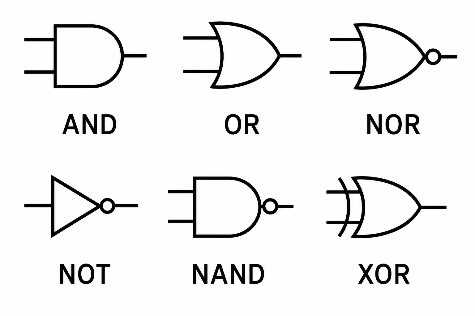
AND Gate
Definition: The output is true (1) only when all inputs are true (1).
Logic Function: Y = A . B
| A | B | Y = A.B |
|---|---|---|
| 0 | 0 | 0 |
| 0 | 1 | 0 |
| 1 | 0 | 0 |
| 1 | 1 | 1 |
OR Gate
Definition: The output is true (1) if at least one input is true (1).
Logic Function: Y = A + B
| A | B | Y = A+B |
|---|---|---|
| 0 | 0 | 0 |
| 0 | 1 | 1 |
| 1 | 0 | 1 |
| 1 | 1 | 1 |
NOT Gate
Definition: A single-input gate that simply reverses (inverts) the input value. It is also called an inverter.
Logic Function: Y = A’ (or Ā)
| A | Y = A’ |
|---|---|
| 0 | 1 |
| 1 | 0 |
NAND Gate (NOT + AND)
Definition: Produces the opposite output of an AND gate. The output is false (0) only when all inputs are true (1).
Logic Function: Y = (A.B)’
| A | B | Y = (A.B)’ |
|---|---|---|
| 0 | 0 | 1 |
| 0 | 1 | 1 |
| 1 | 0 | 1 |
| 1 | 1 | 0 |
NOR Gate (NOT + OR)
Definition: Produces the opposite output of an OR gate. The output is true (1) only when all inputs are false (0).
Logic Function: Y = (A+B)’
| A | B | Y = (A+B)’ |
|---|---|---|
| 0 | 0 | 1 |
| 0 | 1 | 0 |
| 1 | 0 | 0 |
| 1 | 1 | 0 |
XOR Gate (Exclusive OR)
Definition: Output is true (1) only when the inputs are different from each other.
Logic Function: Y = A ⊕ B
| A | B | Y = A⊕B |
|---|---|---|
| 0 | 0 | 0 |
| 0 | 1 | 1 |
| 1 | 0 | 1 |
| 1 | 1 | 0 |
XNOR Gate (Exclusive NOR)
Definition: Produces the opposite output of an XOR gate. The output is true (1) only when both inputs are the same (both 0 or both 1).
Logic Function: Y = (A ⊕ B)’
| A | B | Y = (A⊕B)’ |
|---|---|---|
| 0 | 0 | 1 |
| 0 | 1 | 0 |
| 1 | 0 | 0 |
| 1 | 1 | 1 |
2.2.4 Laws of Boolean Algebra
Just like ordinary algebra has rules (like the commutative or distributive property), Boolean algebra follows its own set of laws, which are used to simplify complex Boolean expressions and digital circuits.
Complement Laws
A variable combined with its own complement using OR always gives 1 (true), and combined using AND always gives 0 (false).
Identity Laws
Commutative Laws
The order of variables does not affect the result of an AND or OR operation.
Associative Laws
When combining three or more variables with the same operation, the way they are grouped does not affect the final result.
Distributive Laws
Similar to how multiplication distributes over addition in ordinary algebra, AND distributes over OR in Boolean algebra (and, less intuitively, OR also distributes over AND).
2.2.5 Statement and Verification of Laws of Boolean Algebra Using Truth Table
Boolean laws can be verified by constructing a truth table for both sides of the equation and checking that the output columns match exactly for every possible input combination.
Example: Verifying the Commutative Law (A + B = B + A)
| A | B | A + B | B + A |
|---|---|---|---|
| 0 | 0 | 0 | 0 |
| 0 | 1 | 1 | 1 |
| 1 | 0 | 1 | 1 |
| 1 | 1 | 1 | 1 |
Since the “A + B” column and the “B + A” column produce identical results for every combination of A and B, the commutative law is verified.
Example: Verifying the Distributive Law (A.(B+C) = (A.B)+(A.C))
| A | B | C | B+C | A.(B+C) | A.B | A.C | (A.B)+(A.C) |
|---|---|---|---|---|---|---|---|
| 0 | 0 | 0 | 0 | 0 | 0 | 0 | 0 |
| 0 | 0 | 1 | 1 | 0 | 0 | 0 | 0 |
| 0 | 1 | 0 | 1 | 0 | 0 | 0 | 0 |
| 0 | 1 | 1 | 1 | 0 | 0 | 0 | 0 |
| 1 | 0 | 0 | 0 | 0 | 0 | 0 | 0 |
| 1 | 0 | 1 | 1 | 1 | 0 | 1 | 1 |
| 1 | 1 | 0 | 1 | 1 | 1 | 0 | 1 |
| 1 | 1 | 1 | 1 | 1 | 1 | 1 | 1 |
The “A.(B+C)” column and the “(A.B)+(A.C)” column match exactly for every combination of A, B, and C, so the distributive law is verified.
De Morgan’s First Theorem: (A + B)’ = A’ . B’
This theorem states that the complement of a sum (OR) equals the product (AND) of the individual complements.
| A | B | A+B | (A+B)’ | A’ | B’ | A’.B’ |
|---|---|---|---|---|---|---|
| 0 | 0 | 0 | 1 | 1 | 1 | 1 |
| 0 | 1 | 1 | 0 | 1 | 0 | 0 |
| 1 | 0 | 1 | 0 | 0 | 1 | 0 |
| 1 | 1 | 1 | 0 | 0 | 0 | 0 |
The “(A+B)'” column and the “A’.B'” column produce identical results for every combination of A and B, so De Morgan’s first theorem is proved.
De Morgan’s Second Theorem: (A . B)’ = A’ + B’
This theorem states that the complement of a product (AND) equals the sum (OR) of the individual complements.
| A | B | A.B | (A.B)’ | A’ | B’ | A’+B’ |
|---|---|---|---|---|---|---|
| 0 | 0 | 0 | 1 | 1 | 1 | 1 |
| 0 | 1 | 0 | 1 | 1 | 0 | 1 |
| 1 | 0 | 0 | 1 | 0 | 1 | 1 |
| 1 | 1 | 1 | 0 | 0 | 0 | 0 |
The “(A.B)'” column and the “A’+B'” column produce identical results for every combination of A and B, so De Morgan’s second theorem is proved.
Both theorems are widely used to simplify Boolean expressions and digital circuits, since they let you convert an OR-based expression into an AND-based one (and the other way round) without changing what the circuit actually does. NAND and NOR gates are often described as “universal gates” precisely because De Morgan’s theorems show they can be combined to build any of the other basic gates.
Quick Revision: Key Points
- Number system bases: Binary = 2, Octal = 8, Decimal = 10, Hexadecimal = 16
- Binary to decimal: multiply each digit by 2 raised to its position, then sum
- Decimal to binary/octal/hex: divide repeatedly by the base, read remainders bottom to top
- Binary to octal: group in 3s; Binary to hex: group in 4s
- One’s complement: flip every bit
- Two’s complement: flip every bit, then add 1
- Two’s complement subtraction discards the final carry; one’s complement adds it back (end-around carry)
- 7 basic logic gates: AND, OR, NOT, NAND, NOR, XOR, XNOR
- XOR is true when inputs differ; XNOR is true when inputs are the same
- Boolean laws: Complement, Identity, Commutative, Associative, Distributive
- De Morgan’s first theorem: (A+B)’ = A’.B’; De Morgan’s second theorem: (A.B)’ = A’+B’
- Laws are verified by comparing truth table outputs for both sides of an equation

Published August 2026. Last verified and updated: September 2026.